English Commentaly
Evanescent light
First of all, we will explain "evanescent light," an important technical keyword.
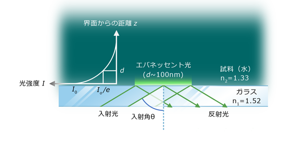
As shown in Fig. 1, when light is incident from a medium with a high refractive index to a medium with a low refractive index, the light is totally reflected at the interface between the two media when the angle of incidence is greater than or equal to a certain angle (critical angle). In the case n1, n2(n1>n2), where the critical angle θc is expressed by equation (1).
sinθc=n2/n1(1)
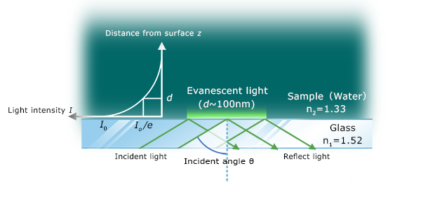
Fig.1
In the case of FIG. 1(n1=1.52,n2=1.33), The critical angle is 61.0°.
Here, it is known that when light incident from the medium on the high refractive index side at a critical angle or more totally reflects at the interface, the phenomenon of "bleeding" into the medium on the low refractive index side is called "evanescent light". Evanescent light cannot propagate long distances, and its strength I decays exponentially away from the surface, as shown in equation (2).
 (2)
(2)
Since evanescent light has unique non-freedom space propagation characteristics and localize characteristics, light energy can be used for purposes and forms different from ordinary light (light propagating in free space). These characteristics have long been used in basic scientific instrumentation.
Typical examples include near-field optical microscopes and total internal reflection microscopes that focus on the ability to observation dark-field illumination at high S/N, and total internal reflection fluorescence microscopes (described later) that actively utilize the ability to selectively observe only information in the vicinity of the interface.
Excitation of waveguide-mode
Next, we will explain the effects of waveguide-mode and evanescent light amplification.
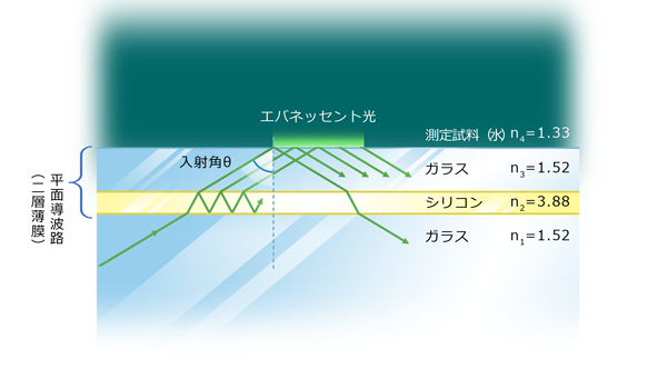
Considering the case where a planar waveguide composed of two thin films as shown in Fig.2 is added to the total reflection surface of Fig.1.
At this time, under specific conditions, the silicon layer functions like a core in an optical fiber, as shown in Fig. 2, and light propagates through the planar waveguide while being multiple-reflected. This condition, that is, the condition under which waveguide-mode is excited, is when the length of the optical path reflected once in the waveguide is an integral multiple of the wavelength of the incident light (=when the phases of the plane waves are aligned).
More inportant thing is "evanescent light is reinforced with multiple reflection of light in the waveguide".
If the incident angle and the thickness of the waveguide layers are fixed, waveguide-mode is excited at a certain wavelength (to be accurate also at the peripheral of the wavelength), and the evanescent light is enhanced at the periphery of the wavelength. Good design of planar waveguides can enhance the evanescent light intensity (electric field intensity) to several hundred times that of incident light, making it a very useful tool for evanescent light applications.
Based on this idea, AIST (Electro-Optical Technology Research Division (Optical Sensing Group)) conducted fundamental research on the materials and layer thicknesses constituting planar waveguides and research on applied technologies in order to enhance evanescent light efficiently.
We have been working with AIST to development waveguide-mode sensors. For more information, see the links and reference below.(If Google searches are performed at AIST or waveguide-mode Sensors, a lot of information-related information can be found.)
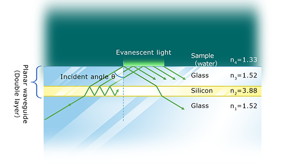
Fig.2
To Page top
Sensing Theories and Advantages of waveguide-mode Sensors
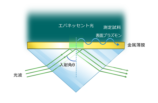
Similarly, photosensors using evanescent light include surface-plasmon resonance (Surface Plasmon Resonance:SPR) sensors. (Biacore series is popular :GE Helthcare Inc.)
In SPR, gold or alminim thin layer is used as the total internal reflection serface, and surface plasmons resonance is excited by evanescent light.
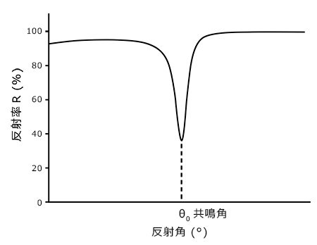
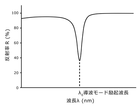
Most SPR sensors adopt the Kretschmann configuration shown in Fig.3 as an optical system that is highly practical from the perspective of applying SPR sensors to biosensors. When the incident angle θ and the reflectivity R are plotted, the resonance curves shown in Fig.4(a) are obtained.On the other hand, in the waveguide-mode sensors, when the incident angle θ is fixed and the reflectivity R and the wavelength λ are plotted in the same Kretschmann configuration, the curves of the downward convexity are obtained as shown in Fig.4(b).
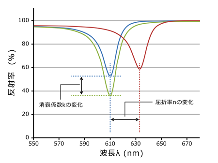
In both sensors, adsorption of a transparent substance, such as a protein, on the sensor surface causes a lateral shift in the bottom of the convex curve (dip bottom). In SPR sencor, the resonance angle θ is shfted, and in waveguide-mode sensor, exitaion wagelength λ is shifted.
For biosensing applications, these sensors are mainly used to detect protein snap and antigen-antibody reactions. Changes in the refractive index (dielectric constant) of a very narrow region where evanescent light (surface plasmon) reaches is actually detected.
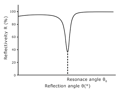
Fig.4(a)
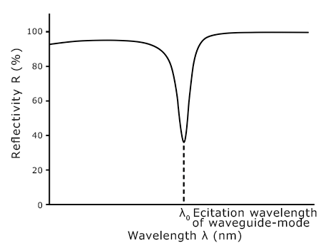
Fig.4(b)
In principle, the sensitivity of waveguide-mode sensors to refractive index changes is several times higher than that of other sensors, but in practical use, the sensitivity is almost the same. By comparing the two, the advantage of waveguide-mode sensors over SPR sensors is that devices with comparable sensing sensitivities can be manufactured in an overwhelmingly small and low-cost manner.
There are two main reasons. One is that the abscissa of FIG.4 differs, i.e. SPR is angle-resolved and mechanisms are required to accurately measure angles, whereas waveguide-mode sensor is wavelength-resolved and spectrometer* can be used. The other is that the SPR is used metal film on sensor chip, and therefore is sensitive to temperature changes of the sample to be measured, whereas waveguide-mode sensor uses only silicon-based materials, and therefore is hardly affected by changes in practical temperature range.
* When it is desired to measure the angle and the wavelength with the same accuracy, the method of measuring the wavelength using a spectrometer is overwhelmingly advantageous in terms of size and cost.
As shown in Fig. 5, only waveguide-mode sensors can detect changes in the extinction coefficient k in addition to the refractive index n (detect changes in the reflectivity R of the dip bottom). (* Detection of the change in extinction coefficient = Detection of the adsorption of colored substances) This feature is very effective in increasing the sensitivity of biosensing, Comparing the adsorption of the same amount of protein (change in refractive index) and metal nanoparticles (change in extinction coefficient), the sensitivity of metal nanoparticles is more than three orders of magnitude higher than that of protain.
A particularly important item in comparing biosensors is the presence or absence of quantitation.In general, paper and plastic products, such as paper chromatography, are not quantitative and are used in qualitative tests to determine whether a certain threshold has been exceeded and whether a change in color or coloration is detected by visual inspection of a person.On the other hand, biosensors that combine electronic devices, such as SPRs and waveguide-mode sensors, are often quantified by some method (such as a calibration curve).
Immunochromatography, which is used in tests such as influenza virus infection, is one of paper chromatography. Since the aggregation of gold nanoparticles by antigen-antibody reaction is judged visually by the presence or absence of red coloration, it cannot be judged positively due to insufficient of sensitivity at the initial stage of infection (when the amount of virus is small), and it is not quantitative.
Waveguide-mode sensors can measure the snap of gold nanoparticles very sensitively and quantitatively.Thus, the combination of waveguide-mode sensors and immunochromatography makes it possible to increase the sensitivities and simultaneously to quantify viruses. For more detail on immunochromatography using waveguide-mode sensors, see product page.
Shows the waveguide-mode sensors and their biosensing products and comparative tables.
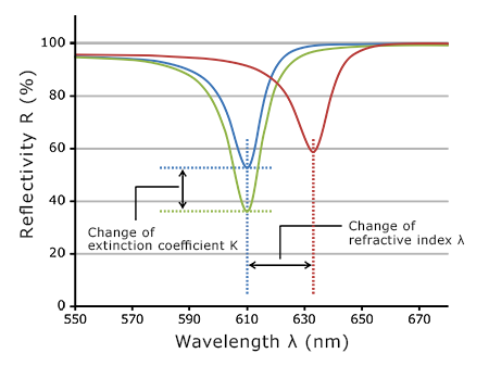
Fig.5
|
Sensitivity |
Quantitivity |
Mobility |
Easy to use |
| Waveguide-mode sensor |
○ |
◎ |
○ |
○ |
| SPR sensor |
☓ |
◎ |
☓ |
△ |
| Immunochromatography |
△ |
☓ |
◎ |
◎ |
| ELISA |
◎ |
○ |
△ |
☓ |
To Page top
A New Option for Total Internal Reflection Fluorescence Microscopy (TIRF) -- Use TIRF for Routine Fluorescence Observation !
This section describes how waveguide-mode technologies can be applied to total internal reflection fluorescence microscope and features. Before this, we briefly review the differences between total internal reflection fluorescence microscopy (Total Internal Reflection Fluorescence microscopy, commonly called TIRF) and common fluorescence microscopy.
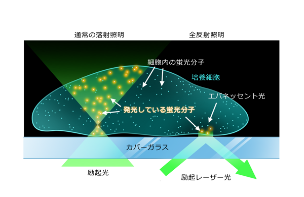
In a general fluorescence microscope and TIRF, the illumination method to excite the fluorescent dyes is different. See Figure 6.Since a typical fluorescence microscope uses epi-illumination of excitation light, it illuminates the entire vertical direction in addition to the observation position (focal position) of the specimen. Therefore, the fluorescent molecules before and after the focus also emit light, resulting in a high intensity of background light and a low S/N ratio. On the other hand, in TIRF, evanescent light is used as illumination (total-reflection illumination), so that only limited fluorescent molecules on the surface to which the cells adhere can be excited, which reduces background light and allows observation with higher S/N.(You can cheak the differences in observation images include Web sites of microscope manufacturers, etc(1) (2) (3).) However, in a study conducted by borrowing TIRF from manufacturers (commercially available products), when cells cultured and fluorescently stained by conventional methods are observed, total reflection illumination does not appear to be completely as shown in Fig. 6. In some case, fluorescence was observed in locations (cell nuclei, etc.) where evanescent light should not reach in theory.* However, the signal-to-noise ratio was still significantly improved compared to epi-illumination.
* This is probably because the cells themselves are transparent, and some of the light that would also penetrates into the cells.This phenomenon appears to be particularly strong when cells adhere to confluence.
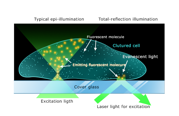
図6
Searching Google images using the "TIRF" reveals many beautiful images of the fine structures of the cytoskeleton. However, such images cannot be taken esaily, and you know that advanced know-how is particularly required for sample preparation.
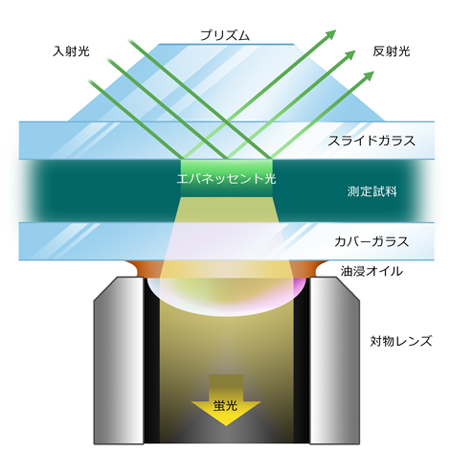
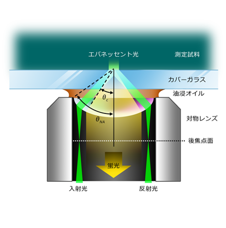
Thus, in TIRF, for illumination with evanescent light (total-reflection illuminatio), it is necessary to enter the light above the critical angle θc to the observed sample. Two types of methods for forming evanescent light with an optical microscope are known, the prism type and the objective lens type shown in Fig. 7.
While the prism type has the advantage of providing a wide field of view, it is require to use an objective lens with a long working distance because the distance between the objective lens and the sample (observation position) is easy to separate. In addition, since an objective lens with a high magnification tends to be darker. So prism type is suitable for observing a wide field of view with a low magnification objective lens.
On the other, the objective lens type is suitable for observing a narrow field of view with a high-magnification objective lens because the objective lens is brighter because it can concentrate light at the focal position of the objective lens, although a low-magnification objective lens is incompatible because light is incident from the edge of an oil immersion lens (NA=1.4 or more) with a high numerical aperture (NA).
All of the TIRF compatible microscopes currently sold by four major manufacturers are objective len-lens type microscopes. Although some prism type models were sold in the initial phases of the TIRF market, the objective lens type models are now the mainstream due to prices of product and user needs. Understanding the reason, in order to obtain an evanescent light of sufficient intensity by single-reflection as shown in Fig. 7, a laser light source must be selected because of the high-strength of parallel light. However, in order to perform multiple dyeing, multiple lasers with excitation wavelengths matched with multiple fluorescent dyes must be prepared. Therefore, the price of the TIRF system is extremely high, with several hundreads of thousands of dollers. When users consider purchasing expensive TIRF, it is clear that the high-end needs that require more detailed observations, i.e., the need for "high magnification & narrow fields of view" are stronger than the need for "low magnification & wide fields of view," and the manufacturers seem to have been focused on objective lenses as a result of corresponding investments.
However, expensive TIRF is not universal, requires fine-tuning of the laser, and requires a narrow field of view to look for the target cells, so it is totally unsuitable for routine fluorescent observations. For rutine use, an objective lens of x5 to x40 magnification is used, and a fluorescence microscope using typical epi-illumination is used. Nevertheless, even in daily observation, the need to take images that were as clear as possible was quite strong, and these people had to refine their sample-create skills and choosing a higher-specification microscope system and objective lens.
Therefore, if a prism type TIRF for daily fluorescence observation is provided at a low cost and images with a higher S/N ratio than that of fluorescence observation using ordinary epi-illumination can actually be taken, what do you want ?
Remember. The reason for the high cost of TIRF system was the need for multiple lasers and dedicated optics to achieve practical evanescent light intensities. And, by using waveguide-mode technologies, evanescent light can be reinforced by a factor of 10 to 100 or more of the incident light intensity*.
* Increase magnification varies depending on the wavelength.
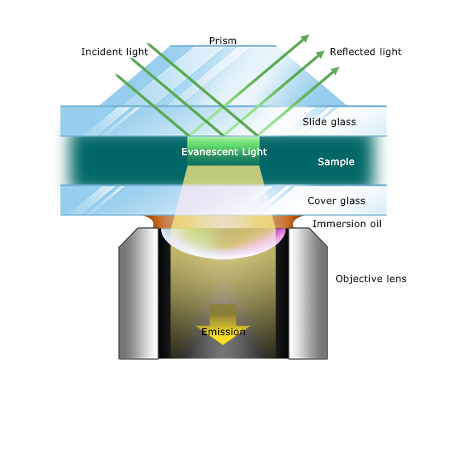
Fig.7(a)Prism type
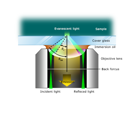
Fig.7(b)Objective lens type
We have succeeded in developing a small, high-precision, low-cost WG-TIRF by leveraging waveguide-mode optical system know-how accumulated through the development of waveguide-mode sensors (Eva-M02) and by adding the functions required for TIRF. You can add the TIRF viewing function to commercially available microscopes* very easily by adding WG-TIRF as an option.
* Widely compatible for upright and inverted microscopes, domestic and overseas product. Refer to the product page for details.
So far, we have described TIRF as a fluorescent microscope that uses evanescent light as the exciting illumination of fluorescent dyes. Howeverevanescent light can be used as dark field illumination in addition to excitation of fluorescent dyes.I think the person who is familiar with the microscope can understand, Dark-field illumination is a method that detects scattered light (Mie scattering) rather than fluorescence. If epi-illumination is changed to total reflection illumination, the signal-to-noise ratio is improved as in fluorescence observation. The theoretical formula for Mie scattering is somewhat complexity and is not discussed here. However, in general, when limited to the size measured for optical microscope, scattered light is more strong than fluorescent light, it is likely to be overwhelmingly more intense than fluorescent light.In other words, since the exposure time can be shortened by observing the scattered light (the time resolution can be increased), the dark field illumination method using the scattered light is advantageous when recording videos.
Using WG-TIRF, you can very easily perform dark-field and fluorescent observations with total-reflection light (compared with epi-illumination), which have higher signal-to-noise ratios.(For specific methods and applications is discrived in Product page.)